< Previous | Contents | Manuals Home | Boris FX | Next >
Once the input data for calibration has been set up trackers or linesyou're ready to set up the calibration processing itself.
NOTE : Be sure to save your current scene file before starting calibration. Not only is that useful in case something goes wrong, but the file name is used as a default lens name, so make it informative about the lens.
Start the calibration process with Shot/Lens Master Calibration menu item, or simply by starting the Lens Master Calibration script within the Lens section of the scripts.
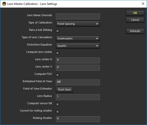
This will cause the initial lens calibration dialog to appear, which is where you tell SynthEyes what properties of the lens you want it to compute as part of the calibration. The input controls are laid out pretty much in the order you need to think about them. When values aren't being computed, the supplied value is used; when the value is being computed, the supplied value serves as a starting point for finding the correct value.
Note that in addition to the descriptions below, you can reference the tooltips of the various fields while running the script.
The Linear type is the usual SynthEyes type for small to moderate amounts of distortion, were the distorted position is computed from the undistorted position. Inverse linear is the same type of calculation, except that the undistorted position is computed from the distorted position. The inverse linear type is used by packages such as Nuke that aren't concerned with undistortion, just with undistorting an image as rapidly as possible.
The Anamorphic selection is for use with anamorphic lenses, of course. When this type is selected, an additional control panel will appear for it; this is discussed later.
NOTE: Lens Master Calibration does not currently support or use the same lens models as the new “Advanced” lens models introduced in SynthEyes 2304.
The fisheye, equisolid, orthographic, and stereographic selections are all types of fisheye lenses; you can read about the details on the wikipedia article on fisheye lenses. If you know it, you can select it directly. Otherwise, you can try each of the selections and see what gives the best fit. If you do that, however, do not permit any additional distortion terms (see next control) while comparing them. First determine the type without distortion, then you can do the calculation with distortion.
Permitting the higher-order terms such as quartic to be computed allows more complex distortions to be modeled more accurately, but if there isn't as much distortion, it causes spurious, unnecessarily complex, coefficients to be computed that are reacting to noise, rather than actual distortion. We recommend starting with the simplest quadratic distortion, and comparing that to the more complex versions. When spurious coefficients are present, it's typical to see positive and negative pairs in cubic and quartic coefficents, ie one canceling the other.
You should stick to simpler distortions with fisheye lenses, especially if you are computing the field of view, as permitting a complex distortion allows the shape of the curve to be changed from the nominal shape, which is what allows the field of view to be computed at all.
Compute FOV. Checkbox. When checked, the lens field of view will be computed. This is only possible for fisheye lenses, or using the Random Dot or Known XYZs calibration methods. It's only possible for fisheye lenses (and not the usual linear lenses) because the
specific mathematics of the lens serve as a reference, if you like. (Random Dots and Known XYZs do make the calculation possible.)
Field of View Estimator. Button. Brings up a small panel to help you estimate the field of view from lens focal length and sensor size.
©2023 Boris FX, Inc. — UNOFFICIAL — Converted from original PDF.